ตัดเอามาเฉพาะที่ตรงประเด็น
The question is often asked; "what load do the valves 'see' in Class AB?". The answer lies in the name 'Class AB' - a combination of Class A and Class B.
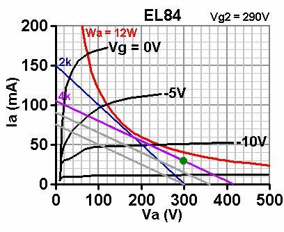
While both valves are conducting the amplifier operates in Class A, and both valves 'see' a load of ½ the anode-anode impedance of the transformer (1/2 Za-a). However, as soon as one valve cuts off, that half of the transformer's primary is no longer part of the circuit. Because the impedance ratio is the square of the turns ratio, the load presented to the remaining 'on' valve must be only ¼ Za-a. So the stage operates in Class B at higher signal levels. Drawing a load line to show this is simple:
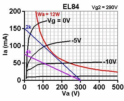
First draw a load line corresponding to ¼ Za-a. In this case that is ¼ 8k = 2k. This is the Class B part of the load [blue line in the image above].
This line may pass above the 'knee' of the grid curves for triode-like operation (good for hifi).
It may pass through the knee, which gives maximum power efficiency and is what the textbooks will tell you to do.
It may slightly pass below the knee. This is typical of guitar amps, but we must ensure that, during operation, the screen voltage can 'sag' so that as the operating point moves towards the left, the grid curves are pulled down so the line ends up passing through or above the knee. 1k screen stopper resistors are normally sufficient to acheive this.
If your line passes a long way below the knee, then the screen voltage must be lowered, or a very sizeable screen-grid stopper must be used. See the section on the pentode on how to do this. This load line may cross the max dissipation curve over a portion of its length- this is allowable.
Second, draw a load line corresponding to ½ Za-a. In this case it is ½ 8k = 4k. This is the Class A part of the load [purple line]. But as it stands, we appear to have biased the stage just to the point of cut-off, so it is only Class B.